Radio Control Calibration in Mission Planner
This article shows how to perform radio control calibration usingMission Planner.
before take a calibration of Radio Control, you should connect RC Receiver to pixhawk, you can make a reference to here,
http://pix.rctoysky.com/how-to-connect-remote-control-receiver.html
Overview
RC transmitters are used to control vehicle movement and orientation. Copter and Plane minimally control throttle, pitch, roll and yaw, while on Rover we just control throttle and roll. Each of these control signals are mapped to transmitter stick/switch(s) and in turn to autopilot channels from the connected receiver.
Calibrating each of the transmitter controls/channels is a straightforward process - simply move each of the enabled sticks/switches through their full range and record the maximum and minimum positions.
Transmitter configuration
There are two main transmitter configurations:
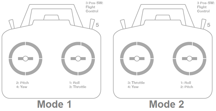
- Mode 1 : left stick controls pitch and yaw, the right stick will control throttle and roll.
- Mode 2 : left stick controls throttle and yaw; the right stick will control pitch and roll.
Transmitter(Mode 1): Recommended Channels
Transmitter(Mode 2): Recommended Channels
Channel mappings
Copter default channel mappings are:
- Channel 1 : Roll
- Channel 2 : Pitch
- Channel 3 : Throttle
- Channel 4 : Yaw
- Channel 5 : Flight modes
- Channel 6 : (Optional) Inflight tuning or camera mount (mapped to transmitter tuning knob)
Unused channels can be mapped to control additional peripherals.
Note
- The default channel mappings can be changed using the instructions in RCMAP Input Channel Mapping .
- Once you’ve calibrated the flight mode you can use the instructions in RC Transmitter Flight Mode Configuration to specify which vehicle modes are enabled by each switch position.
Preconditions
Safety first
For safety reasons you should disconnect the battery and/or remove propellers before preforming radio calibration.
Centre trims
Centre trims in manual RC mode before preforming RC calibration. If trims are not centred you may need to do the RC calibration again after you have used the vehicle (this is easy to do at the field).
Note
Trims are centred when a moving vehicle does not change direction/speed/orientation when travelling hands-off with all controls/sticks in neutral positions. If there is any deviation in direction, speed or orientation, adjust the associated servo to compensate.
Connect autopilot and turn on receiver
Connect the autopilot via USB and turn on your RC transmitter. Verify that the transmitter is bound to the receiver (the receiver displays a solid green light) and that it is set to use the correct model for your vehicle.
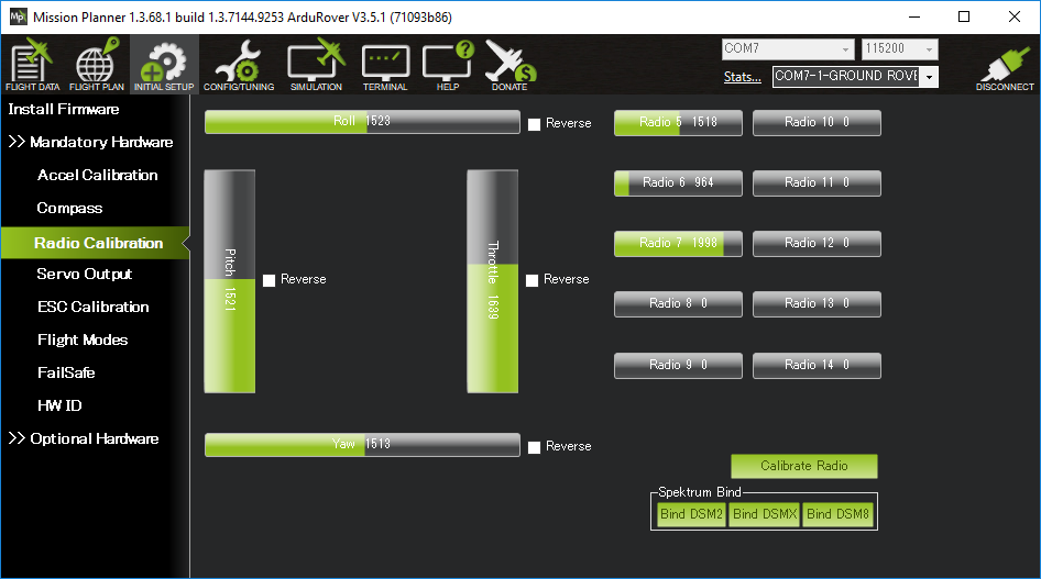
Open Mission Planner’sINITIAL SETUP | Mandatory Hardware | Radio Calibrationscreen. If your RC receiver (Rx) and transmitter (Tx) are bound, you should see the green bars move when you move the transmitter sticks.
MissionPlanner: Radio Calibration Screen (Copter)
Mission Planner: Radio Calibration Screen(Plane)
Tip
If the bars are not moving then check what LED lights the receiver is displaying:
- no lights - may indicate that it is incorrectly wired to the autopilot (look for connectors that may have been inserted upside down).
- red or a flashing green light - may indicate that your RC transmitter/receiver need be bound (see the manual that came with your RC equipment for instructions).
- a solid green light - recheck the autopilot is connected to the Mission Planner and if the bars are still not moving, try clicking on the Calibrate Radio button.
Calibration steps
Open Mission Planner’sINITIAL SETUP | Mandatory Hardware | Radio Calibrationscreen.
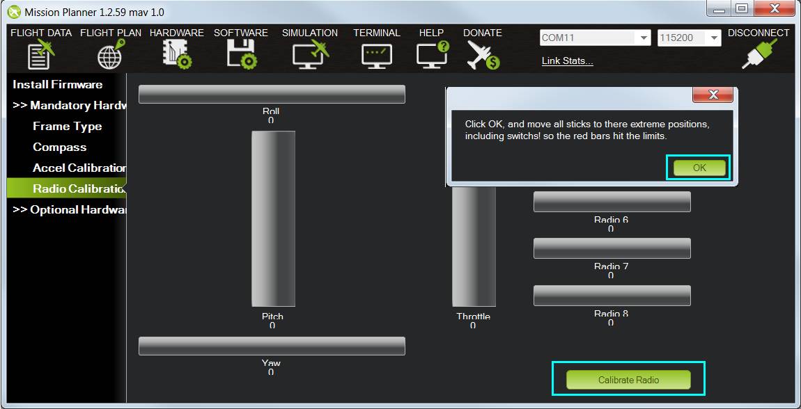
Click on the greenCalibrate Radiobutton in the lower right of the window.
Mission Planner will display a prompt to check radio control equipment is on, battery is not connected, and propellers are not attached. SelectOK.

Mission Planner: Select Calibrate Radio and OK to begin calibrating.Move the control sticks and toggle switches on your transmitter to their limits of travel and observe the results on the radio calibration bars. Red lines will appear across the calibration bars to indicate maximum and minimum values:

Mission Planner: Input range marked with red linesTip
The green bars should move in the
same direction
as the
transmitter sticks (except for Pitch where the bars move opposite to stick movements - low values are forward, high values are back). If the green bars move in the wrong direction, reverse them using your RC transmitter’s channel-reverse function (see your RC gear’s manual for guidance).You should also calibrate the channel you have selected for controlling vehicle mode, and any other channels you have connected to the autopilot.
SelectClick when Donewhen all required channels are set at the minimum and maximum positions.
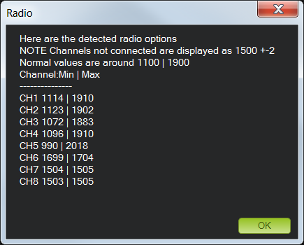
Mission Planner will show a summary of the calibration data. Normal values are around 1100 for minimums and 1900 for maximums.
Turn off your transmitter and disconnect the battery if it was connected.


